
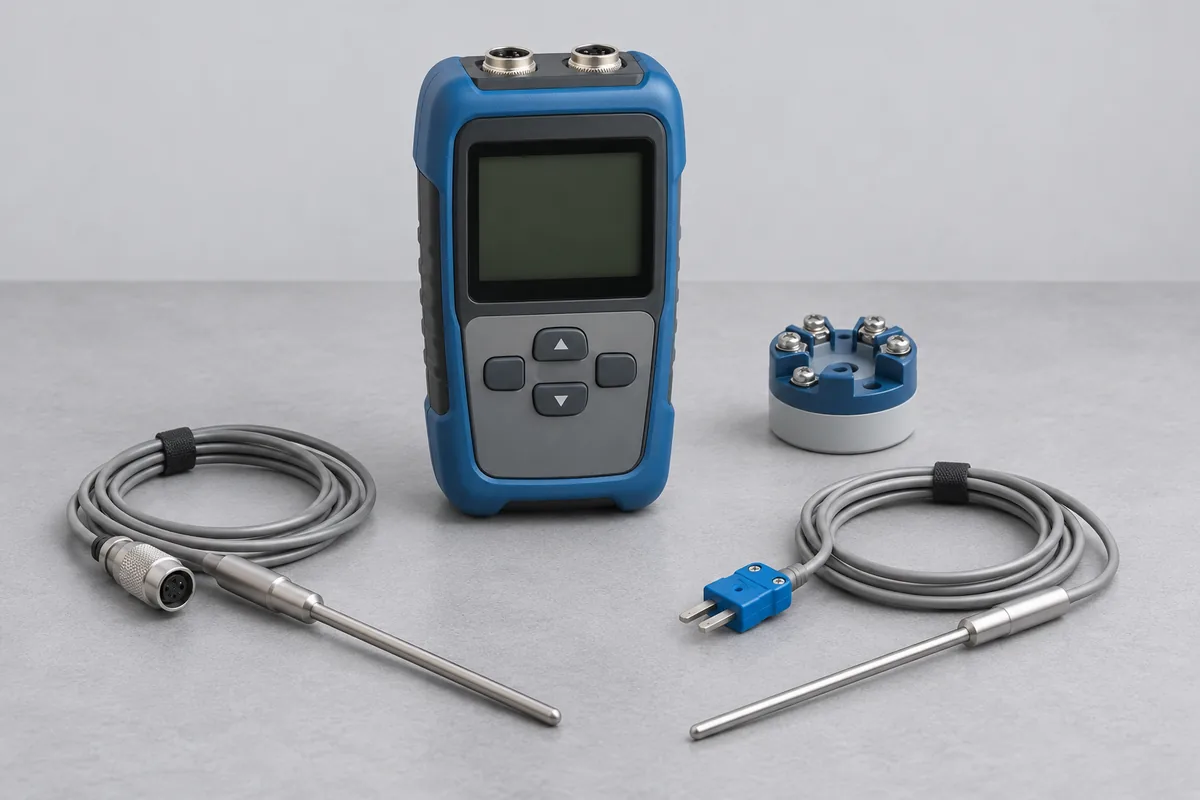
Read the sensor identification
Copy the type letter from the sensor tag or purchase record. If the tag is missing, give the manufacturer's part number. Describe the measuring junction if known, along with sheath material, diameter and usable insertion length.
Include the cable and indicator details
Say whether an extension or compensating cable stays with the probe in use. If the request includes the panel reading, identify the indicator, its input channel and the sensor connected to it. Add the temperatures specified in your process record.
Where the connector sits in normal use
A maintenance kit might contain a probe, an extension lead and a handheld reader, each with its own tag. If an operator plugs the probe directly into the reader during one check and uses the long lead for another, sketch both arrangements. Mark the connector that remains in the measuring area and identify the temperature range at the probe tip.
For a probe mounted in a sheath with a flange or compression fitting, give the length that can actually be immersed. A drawing from the original order is useful if the tag only carries the element type.
Thermocouple and display assemblies at higher temperatures
For a thermocouple used with an indicator, recorder or transmitter, name the complete combination that needs the temperature result. Keep the type letter, usable sheath length and normal cable arrangement with the order. Give the requested points rather than the maximum value printed on the display. The display range alone says little about the temperature that the installed probe and sheath can withstand.
CC-4643 has thermal entries for the listed thermocouple and instrument combinations at 250 to 650 °C and 650 to 1200 °C, under permanent and site facilities. These use comparison with a reference thermocouple and a dry-block furnace. RTS must match the actual assembly and proposed points to the entry and usable setup. Electrical simulation of a thermocouple input is a separate measurement from heating the physical sensor.
For a heat-treatment line at IMT Rohtak, identify whether the removable assembly or the installed furnace indication is required. A location-specific indicator comparison and a survey across the furnace zone need different plans. Include the process contact who can confirm the measurement arrangement before the work is booked.
A removable probe or a fixed installation
Tell us whether a spare can be sent while the line runs or whether access depends on a shutdown. The site address and access window help RTS review the arrangement before you remove any assembly.