
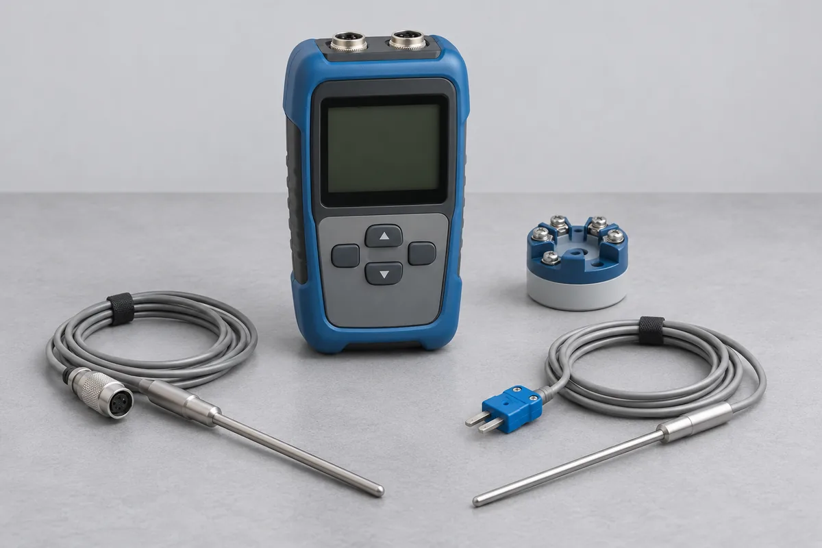
Probe and wiring details
Provide the element marking and say whether the probe uses two, three or four wires. If a single sheath contains two elements, identify which one you use or whether both are needed. Add the probe length, diameter and any insertion limit.
Does the reading pass through a transmitter?
A display may show temperature while a head-mounted transmitter sends a current signal to the plant. State which part of that chain your procedure covers. For a transmitter, give its model and the temperature span configured for its output.
A three-wire probe on a replacement cable
An instrument register may say “Pt100” for both the short probe on a machine and a long probe on a vessel. Their stems, leads and usable immersion can differ considerably. Mark how much of the stem normally reaches the process and whether a fitting limits insertion. Give the straight length below that fitting.
If the probe now has an extension running to a remote display, identify where the extension joins the original lead. You can request a result for the removable probe and a separate assessment of the reading at the display. State which result the maintenance record calls for.
Pt100 probe and readout combinations in the scope
A result for the assembled temperature reading needs the probe and the readout identified together. Record the probe tag, display serial number, input channel and lead arrangement used during normal work. If the readout stores a correction for that probe, include the configuration reference. A spare probe with the same Pt100 marking should not silently replace the one named on the request.
The permanent-facility thermal entries in CC-4643 list the stated RTD or Pt100 sensor and instrument combinations over −30 to 100 °C and 100 to 250 °C. The site entry for those combinations lists 100 to 250 °C. Match the assembly and required points to the relevant entry. These entries should not be read as a blanket statement for every bare RTD, Pt1000 probe or site temperature range.
Where maintenance at IMT Kharkhoda swaps a readout between machines, list the combinations actually requiring results. Identify which parts can travel and which stay installed. That gives RTS a defined instrument list for the quotation and a record your team can check when the equipment returns.
Temperature points for the quotation
Use the points from your process or quality record, with units. Tell us whether the assembly can be removed and whether the certificate should identify the sensor, transmitter or both.
Thermowells and probe fit
A thermowell is the protective fitting around a temperature probe, not an independent temperature indicator. Give its drawing, bore, insertion length and the probe assembly used inside it. If dimensional inspection or another test is required, identify those features separately. For temperature comparison, tell RTS whether the thermowell must be included in the setup and why; a probe result should retain the configuration actually used during measurement.
Standard platinum resistance thermometers
A standard platinum resistance thermometer used as a reference needs its calibration history, readout or bridge arrangement and intended temperature interval recorded. Say whether you require comparison points, resistance ratios or fixed-point work. These are not interchangeable requests. The listing of an SSPRT as a reference in CC-4643 does not establish a service for calibrating every SPRT; RTS must review the required method and service route before acceptance.
Unspecified temperature sensors
When an asset is listed only as a temperature sensor, identify its principle before choosing the calibration arrangement. Give the sensor label, probe dimensions, wiring and any paired indicator. State whether you need a temperature result or an electrical output such as resistance or voltage. RTS can route the request to the relevant configuration and scope review without creating another page for a description already covered by RTD or thermocouple information.
Thermistors with or without readouts
A thermistor may be evaluated through its resistance or through the temperature shown by a connected readout. Identify the sensor curve or coefficients used, the cable arrangement and the requested temperature points. Keep the readout settings with the sensor identity where they form a pair. RTS must review the applicable comparison method; a Pt100 description should not be applied automatically to a thermistor simply because both are resistive sensors.