
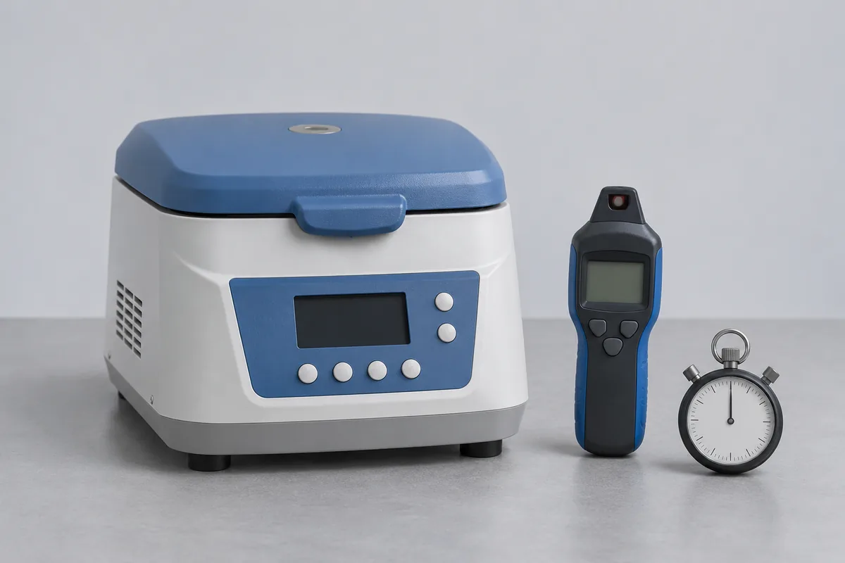
Send the rotor identification with the speed settings
List the machine serial number and the marking on the rotor used for the run. Include any buckets or carriers that belong with it. Two departments may use different rotors in the same machine. Identify which assembly the report should cover and, where relevant, the operating configuration specified by the manufacturer.
A front panel may show revolutions per minute or relative centrifugal force, often marked ×g. The conversion depends on radius. If your work instruction gives ×g, send the rotor model and the relevant manual page so the speed and the quantity to report can be agreed.
Define the start and finish of the timed run
For a routine cycle at 3,000 rpm, the request could call for speed at the settled setting and elapsed time over the ten-minute hold. State what signals the end of that hold. Time until standstill includes the braking period if the procedure calls for it. Refrigerated chamber temperature is another measurement, with its own setpoint and conditions.
Access for an installed centrifuge
A clear photograph of the lid and any observation port helps us review the manufacturer's permitted way to observe speed with the guard closed. For a laboratory in IMT Rohtak, give the room, available run window and the person who can release the machine. If it travels, agree how the rotor should be protected for transport.
Blood bank centrifuge engineering measurements
Identify the blood bank centrifuge and the rotor, buckets and programme released by the engineering team. List speed, time and any temperature requirements separately, using the approved equipment procedure. Refrigerated air, chamber indication and specimen-temperature conditions are not interchangeable. RTS must review the permitted observation method and configuration; a speed check does not establish suitability of a blood-processing procedure.
Centrifuge bucket identification
A centrifuge bucket carries the sample arrangement and belongs with its approved rotor. Record its marking, adapter and any owner-required inspection record. It does not normally have a standalone calibration function. If a dimension, mass or other quantity is needed for the test setup, state it explicitly; a speed result for the machine does not assess bucket condition or compatibility.
Centrifuge rotor and the reported quantity
Record the rotor identity beside the centrifuge asset number, including the configuration used when a speed or force-related result is requested. Rotational speed and calculated relative centrifugal force are different quantities, with the latter depending on the applicable radius. A rotor’s structural inspection and service-life records are separate from the calibration of the machine’s speed indication.
Centrifuge tube as a setup component
A centrifuge tube is a container selected for the approved rotor and method. Give its designation and adapter arrangement when they affect the agreed equipment check. Nominal tube capacity is not a calibration of delivered volume. If volume is genuinely the required quantity, identify that separate laboratory method rather than assuming a speed-and-timer booking covers the tube’s graduations.
Fixed angle rotor geometry
For a fixed angle rotor, retain the rotor model and the sample position used by the instrument’s speed-to-force calculation. Give the manufacturer’s relevant geometry information when relative centrifugal force is requested. The result should identify the actual configuration. Dimensional or condition inspection of the rotor requires its own defined requirement and cannot be inferred from the displayed speed.
Swing bucket rotor and carrier combination
Identify a swing bucket rotor together with its buckets, adapters and the manufacturer’s configuration used for reporting. Changing a carrier can change the relevant sample position even when the machine is unchanged. Retain those identities with the equipment check. The enquiry should separate speed, time and temperature measurements from the owner’s inspection of pivots, buckets and other structural components.