
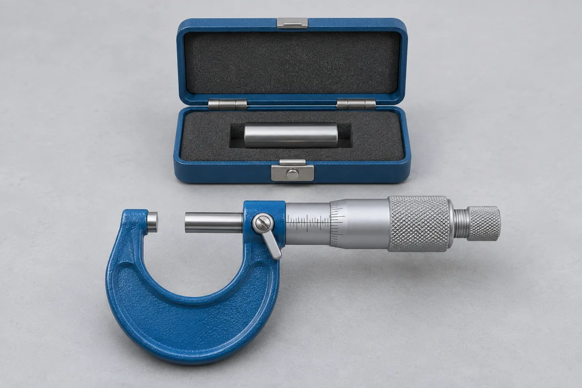
Identify the measuring arrangement
State whether the instrument measures outside diameter, an internal bore or depth. Describe the contact faces, particularly for blade, ball or disc anvils. A photograph is useful if the instrument has been stored separately from its box.
List the head, rods and standards
Give the range marked on each part and the head's scale division or display increment. If you use a setting rod or ring, identify it separately and say whether it also needs calibration. Agree which accessories to send before packing the set.
Setting rods from 25 to 150 mm
The permanent-facility scope of CC-4643 includes setting rods from 25 to 150 mm. If the rod used to set a micrometer is also due for calibration, enter its marked length and identifier separately from the micrometer body.
A shared rod may be used by several tool sets. Note which stores record owns it and ask for its result under that identifier. Keep the contact faces protected in transit and identify any damage or wear that prompted the request.
A result for the size you inspect
A shop checking a shaft close to 32 mm may use a 25–50 mm outside micrometer every day. A zero check with the setting standard gives one piece of information. The quality engineer may also need a result near the shaft size. Put that working point beside the range on the request and identify the ratchet or friction device fitted to the head.
For a set with partly overlapping ranges, write the frame or rod combination next to each requested size. That lets the reader match a certificate row to the instrument actually used on the part.
Match the request to the part
Include any sizes specified by your inspection sheet and the way you identify the micrometer on it. If the spindle binds or the ratchet slips, describe the fault when requesting a quotation.
Optical flat reference surfaces
An optical flat is a reference used to examine a surface under a specified optical arrangement. Identify the working face, material, size and existing flatness record. State whether you need the reference face assessed or intend to use it during another instrument check. A visual interference pattern is not an assigned value for the optical flat itself; the reference measurement requires its own method review.
Optical parallel identification
For an optical parallel, identify both working faces, its thickness and the characteristics assigned on the existing certificate. Flatness of each face and the relationship between the faces are distinct requirements. List the members of a set individually. Their use in examining micrometer contacts does not establish a calibration service for the parallels; RTS must confirm the reference measurement and reporting route separately.