
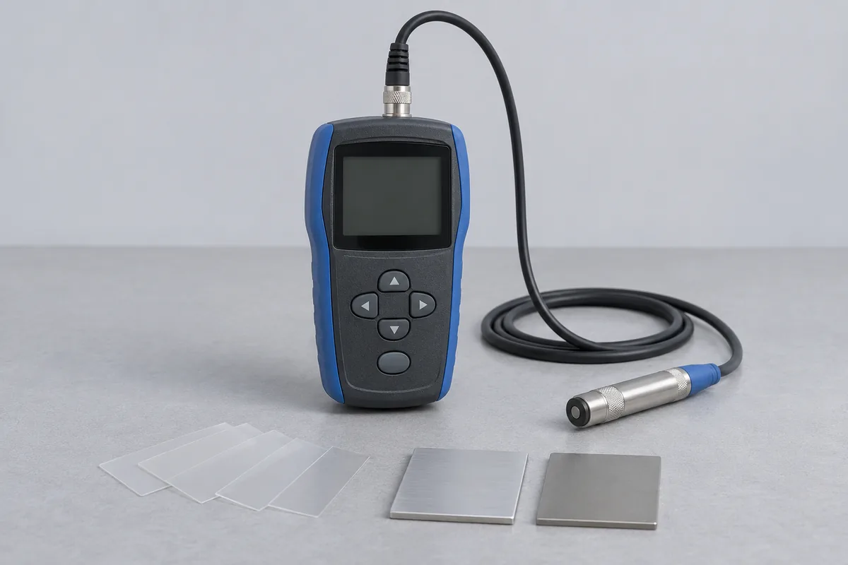
Match the probe to the part
Give the gauge and probe model, including any F or N marking. Describe the coating, the metal beneath it, and whether the inspector measures a flat face, a small radius or a narrow edge. Include the thicknesses of interest in the units used on the inspection sheet.
Account for foils and reference pieces
List the thickness marked on each foil in the case. Tell us which foils and base plates you use for routine checks and whether any of them need a separate result. Discuss a suitable sample before sending a coated production part.
DFT gauges, reference foils and cutter geometry
CC-4643 includes permanent-facility entries for coating thickness gauges over 0.05–2 mm, with a least count of 0.001 mm and coarser, and a separate standard-foil entry over 0.05–2 mm. For a dry film thickness (DFT) kit, identify the meter, probe and individual foils on separate lines so each requested result can be matched to the correct item.
The same scope also lists the linear measurement of a cross-hatch cutter over 0–3 mm. A cutter sent with the coating kit therefore needs its own geometry request and identifier. State the feature and nominal spacing to be checked, protect the cutting edges for transport, and keep this dimensional result with the cutter's inspection record.
Keep substrate adjustment separate from the reference check
A probe's response can be influenced by the substrate shape, surface texture and material. A smooth flat reference plate therefore gives a defined checking condition, while an actual component may need the adjustment described in the instrument's manual. Tell us which saved adjustment or calibration mode your inspector selects for each product family.
If you need the incoming condition recorded, make that clear before an adjustment is considered. Include a previous certificate and your routine check readings where available. Identify the requested result for the gauge, each separate probe and any reference foil or plate. A foil's marked value is not enough to establish its current thickness or condition. Creases, wear and an unclear identifier should be noted before packing. Agree the reference arrangement and points that cover the thickness limits used for inspection.
Releasing gauges from a finishing line
Identify who holds the gauge and where the probe set should be returned. Pack delicate foils flat in their holders, away from loose probes and cables. If finishing and final inspection use different configurations, keep each probe and its reference accessories grouped under the correct instrument entry.
Wet film thickness gauge geometry
Identify whether the wet film thickness gauge is a comb, wheel or another design. Copy the marked graduations and specify the steps or measuring geometry requiring examination. A wet-film tool works differently from an electronic dry-coating gauge. Its dimensions and condition need a separate method review; the electronic coating-gauge scope entry should not automatically be applied to the wet-film instrument.
Thickness standard and calibration foil
For a thickness standard, state whether it is a flexible foil, rigid shim or another reference. List its assigned value, material, identifier and the gauge with which it is used. CC-4643 has a standard-foil entry, but that does not cover every reference construction. RTS must match the item and required measurement to the entry; keep damaged or creased references identified for condition review.