
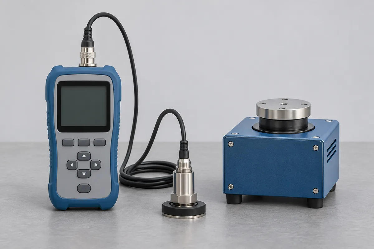
Follow the signal from pickup to display
Some handheld meters have an integral probe. Others have an accelerometer, a cable and a separate reader. Record the identifiers on all three pieces and the sensor sensitivity entered in the reader, if it is configurable. A spare accelerometer from the same kit may carry a different sensitivity.
If the whole assembly is needed for routine rounds, ask for the assembled measurement chain to be covered. An electrical signal applied to the reader can check its response, while a mechanical input through the pickup includes the sensor and its mounting. Agree which arrangement the result will describe.
Use the units from the maintenance log
Give the frequency and vibration level together for each requested point. Copy the display convention, such as RMS, peak or peak-to-peak, and any filter setting that applies. For a three-axis sensor, mark the axes required. Include the supplied stud, magnet or probe tip in the equipment list so RTS can review how the sensor can be mounted to the reference source.
Portable meter or installed monitor?
A portable meter from a maintenance route can often travel as one kit. For a permanently mounted pickup, name the channel and indicate where the signal reaches the panel. Before requesting a visit at IMT Faridabad, identify the equipment owner and access window so the available checks and handback can be discussed.
Accelerometers and signal conditioning
An accelerometer enquiry should identify the sensor, cable, conditioner and the electrical output used. Give the sensitivity units, excitation arrangement and frequencies at which results are needed. Include the mounting method from the application because it belongs to the measurement arrangement. RTS will review the available vibration reference method and required assembly; an electrical check of the conditioner alone does not determine the sensor's mechanical sensitivity.
Triaxial accelerometers
For a triaxial accelerometer, label the three axes and give the required frequencies and sensitivity result for each. Retain the connector pinout and axis convention used by the recording system. A result for one axis should not be copied into the other channels. Identify mounting adapters separately and request that the accepted configuration is recorded, so the returned results can be assigned to the correct directions in your software.
Balancing machine measurement review
For a balancing machine, identify the rotor arrangement, supports, measurement channels and the quantity reported for each correction plane. Include the reference rotor or trial-mass procedure required by the manufacturer. A vibration sensor comparison does not by itself assess the machine's complete unbalance measurement. RTS must review the machine-specific method, reference resources and reporting route before any system assessment is agreed.